
Metrics and dashboards
Prometheus collects native core metrics, host metrics and the project InfoAPI exporter. Grafana supports detailed internal inspection.
A CableFree SC-418 provides the relocatable 5G access network. Amarisoft runs on the small cell; Open5GS and campus services remain on the university network.
Switch between the real setup, its antenna adapter and connector panel, then explore the proposed mobile platform.
Loading the hardware model…
Drag horizontally to rotateToday: a speaker tripod carries the antenna through a metal adapter. The SC-418 sits nearby. This view reconstructs the photographed setup; the bracket and tripod dimensions are approximate.
Model basis: photos of the current setup and the antenna mechanical drawing (600 × Ø89 mm). The small-cell enclosure uses the 325 × 210 × 156 mm reference from the CableFree product-family datasheet. Exact SC-418 enclosure, bracket and wagon geometry still require verification.
The CableFree SC-418 sits on the lab bench beside the omnidirectional antenna on a height-adjustable tripod. Two antenna cables connect the radio hardware to the antenna.
The photograph shows the current setup at Hochschule RheinMain. A shared wagon with an adjustable mast is the next development step.
The small cell and its antenna form the transportable radio site. The core, monitoring services, and application endpoints stay on campus. Moving the radio site requires a backhaul path to that stationary side.
Emerald Outdoor small cell with an integrated 5G NR gNB and radio unit.
Two-port, 360° omni antenna specified by CableFree for 3300–3800 MHz.
The SC-418 runs Amarisoft gNB software under its LTE service.
AMF, SMF, UPF and supporting network functions run on the stationary campus VM.
N2 carries control signalling to the AMF. N3 carries encapsulated user traffic to the UPF. After decapsulation, the N6 side connects the UE data path to campus services. Management and monitoring are separate.
Scroll sideways to explore the diagram, or open the full-size version.
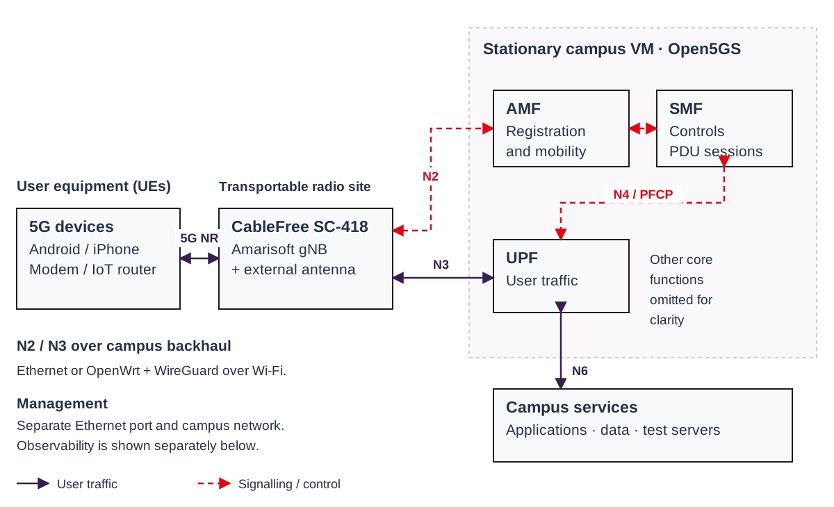
The gNB exchanges control signalling with the AMF.
The gNB sends encapsulated user traffic to the UPF.
The UPF forwards decapsulated packets toward campus services.
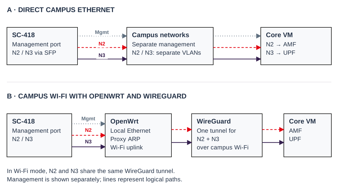
Both modes keep the radio site relocatable and the Open5GS core stationary. The local cabling and transport path change; the 5G roles stay the same.
Two prepared campus LAN outlets connect SC-418 management and its tagged N2/N3 path.
The SC-418 connects locally to an OpenWrt router. The router reaches the campus VM over campus WLAN and WireGuard.
Scroll sideways to explore the diagram, or open the full-size version.
The observability environment combines core and VM metrics, subscriber and session states, service logs and traffic metadata. Grafana helps correlate events across the network and investigate faults.
Scroll sideways to explore the diagram, or open the full-size version.
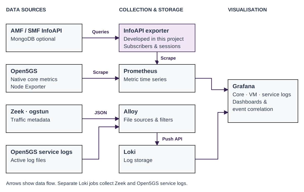
The thesis covers measurement-point selection, scrape and data-source configuration, versioned Grafana dashboards and a custom InfoAPI exporter. The exporter combines AMF and SMF states and exposes subscribers, gNB connectivity and PDU sessions as Prometheus metrics.
The live page shows selected aggregate values. Internal Grafana dashboards provide the detailed diagnostic view.
Prometheus collects native core metrics, host metrics and the project InfoAPI exporter. Grafana supports detailed internal inspection.
Alloy and Loki collect service logs so registration, session setup and operational changes can be traced.
Passive Zeek observation at ogstun complements endpoint tests. Detailed records stay in the researcher tools; the website shows allowlisted aggregates.
The researcher wiki covers the permitted location, cabling, radio service, commissioned SIM, UE setup and checks at the core.